Asus V6-P5G31E Manuel d'utilisateur Page 1
Naviguer en ligne ou télécharger Manuel d'utilisateur pour PC/postes de travail Asus V6-P5G31E. Asus V6-P5G31E User`s manual Manuel d'utilisatio
- Page / 70
- Table des matières
- MARQUE LIVRES
- V6-P5G31E 1
- First Edition V1 2
- November 2009 2
- Table of contents 3
- Safetyinformation 7
- About this guide 8
- Wheretondmoreinformation 9
- System package contents 10
- System introduction 11
- 1.1 Welcome! 12
- 1.2 Front panel 12
- 1-3ASUS V6-P5G31E 13
- 1.3 Rear panel 14
- LANportLEDindications 15
- Voltageselector 16
- 1.4 Internal components 17
- DDR2-1066MHz capability 18
- DDR2-800MHz capability 18
- DDR2-667MHz capability 19
- Starting up 21
- 2.3 Support DVD information 22
- 2.2 Powering up 22
- 2-3ASUS V6-P5G31E 23
- ASSETUP.EXE to run the DVD 23
- 2.3.2 Utilities menu 24
- 2.3.3 Manual menu 25
- VIAHDAudioUser’sManual 26
- 2.3.5 Otherinformation 27
- Technical support Form 28
- Filelist 28
- Motherboardinfo 29
- 3.1 Introduction 30
- 3.2 Motherboard layout 30
- 3.3 Jumpers 31
- 3.4 Connectors 33
- 3-7ASUS V6-P5G31E 35
- BIOS setup 39
- 4.1.1 ASUS Update utility 40
- ASUS V6-P5G31E 4-3 41
- V-P5G31E 42
- V-P5G31E.rom 42
- ASUS V6-P5G31E 4-5 43
- 4.1.3 ASUS CrashFree BIOS 44
- 4.2 BIOS setup program 45
- 4.2.2 Menu bar 46
- 4.2.1 BIOS menu screen 46
- 4.2.3 Navigation keys 46
- ASUS V6-P5G31E 4-9 47
- 4.3 Main menu 48
- Type [Auto] 49
- LBA/LargeMode[Auto] 49
- 4.3.4 StorageConguration 50
- 4.3.5 SystemInformation 51
- 4.4 Advanced menu 52
- CPUFrequency[XXX] 53
- DRAM Frequency [Auto] 53
- 4.4.2 CPUConguration 54
- ASUS V6-P5G31E 4-17 55
- 4.4.3 Chipset 56
- DVMT Mode Select [DVMT Mode] 57
- Front Panel Type [HD Audio] 57
- Parallel Port Address [378] 58
- Parallel Port Mode [ECP] 58
- 4.4.5 USBConguration 59
- 4.4.6 PCI PnP 60
- 4.5 Power menu 61
- 4.5.4 APMConguration 62
- 4.5.5 Hardware Monitor 63
- 4.6 Boot menu 64
- ASUS V6-P5G31E 4-27 65
- 4.6.3 Security 66
- Change User Password 67
- Clear User Password 67
- Password Check [Setup] 67
- 4.7 Tools menu 68
- 4.8 Exit menu 69
- 4-32 Chapter 4: BIOS setup 70
Résumé du contenu
V6-P5G31EASUS PC (Desktop Barebone)User’s ManualR
xSystem package contentsCheck your V6-P5G31E system package for the following items.If any of the items is damaged or missing, contact your retailer i
RSystem introductionThis chapter gives a general description of the ASUS V6-P5G31E. The chapter lists the system features including introduction on th
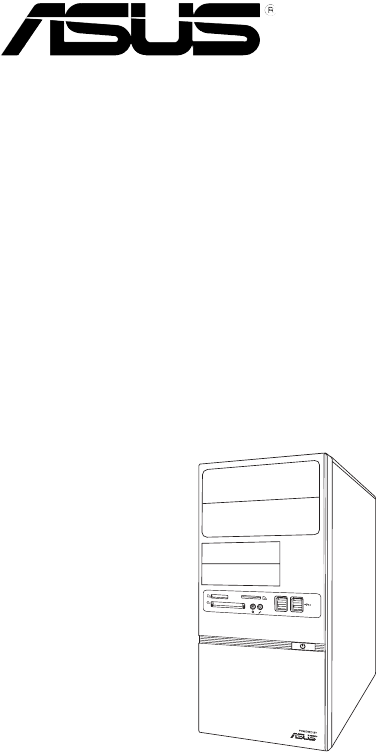
1-2 Chapter 1: System introductionR1.1 Welcome!Thank you for choosing the ASUS V6-P5G31E!The ASUS V6-P5G31E is an all-in-one barebone system with a v
1-3ASUS V6-P5G31E1. Two empty 5.25-inch drive bays. These bays are for 5.25-inch IDE/SATA optical drives.2. Two empty 3.5-inch drive bays. These bay
1-4 Chapter 1: System introduction1.3 Rear panelThe system rear panel includes the power connector and several I/O ports that allow convenient connec
1-5ASUS V6-P5G31E4. Power Switch. This switch is for switching on/off the power supply unit.5. Chassisfanvent.This vent is for the fan that provi
1-6 Chapter 1: System introductionVoltageselectorThe PSU has a 115 V/230 V voltage selector switch located beside the power connector. Use this switc
1-7ASUS V6-P5G31E1.4 Internal componentsThe illustration below is the internal view of the system when you remove the side cover and the power supply
1-8 Chapter 1: System introduction1.5 QualiedVendorsLists(QVL)DDR2-1066MHz capabilitySize Vendor Model CL Brand SS/DS ComponentDIMM supportA* B*5
1-9ASUS V6-P5G31EDDR2-800MHz capabilitycontinued on the next pageSize Vendor Model CL BrandS S /DSComponentDIMM supportA* B* 1G SIS SLY264M8-JGE-3 N/A
iiCopyright © 2009 ASUSTeK Computer Inc. All Rights Reserved.No part of this manual, including the products and software described in it, may be repro
1-10 Chapter 1: System introductionDDR2-667MHz capabilitySize Vendor Model CL BrandS S /DSComponentDIMM supportA* B* 512MB VDATA M2GVD5G3H166I1C52 N/A
RThis chapter helps you power up the system and install drivers and utilities from the support DVD.Chapter 2Starting up
2-2 Chapter 2: Starting upR2.1 Installing an operating systemThe barebone system supports Windows® XP/Vista/7 operating systems (OS). Always install
2-3ASUS V6-P5G31E2.3.1 RunningthesupportDVDTo begin using the support DVD, place the DVD in your optical drive. The DVD automatically displays the
2-4 Chapter 2: Starting up2.3.2 Utilities menuThe Utilities menu shows the applications and other software that the motherboard supports. ASUS InstAl
2-5ASUS V6-P5G31EASUSTurboKeyInstalls ASUS Turbo Key. ASUS Turbo Key allows you to turn the PC power button into an overclocking button. After the e
2-6 Chapter 2: Starting up2.3.4 ASUSContactinformationClick the Contact tab to display the ASUS contact information. You can also nd this informat
2-7ASUS V6-P5G31E2.3.5 OtherinformationThe icons on the top right corner of the screen give additional information on the motherboard and the conten
2-8 Chapter 2: Starting upTechnical support FormDisplays the ASUS Technical Support Request Form that you have to ll out when requesting technical su
RThis chapter gives information about he motherboard that comes with the system. This chapter includes the motherboard layout, jumper settings, and co
iiiTable of contentsNotices ... viAbout this gui
3-2 Chapter 3: Motherboard info3.1 IntroductionThe Vintage V6-P5G31E barebone system comes with an ASUS motherboard. This chapter provides technical
3-3ASUS V6-P5G31E3.3 Jumpers1. ClearRTCRAM(3-pinCLRTC)This jumper allows you to clear the Real Time Clock (RTC) RAM in CMOS. You can clear the C
3-4 Chapter 3: Motherboard info2. USBdevicewake-up(3-pinUSBPW1-4,USBPW5-8)Set these jumpers to +5V to wake up the computer from S1 sleep mode (C
3-5ASUS V6-P5G31EInstall the Windows® XP Service Pack 2 or later version before using Serial ATA.3.4 Connectors1. SerialATAconnectors(7-pinSATA1
3-6 Chapter 3: Motherboard info3. IDEconnector(40-1pinPRI_IDE)The onboard IDE connector is for the Ultra DMA 100/66 signal cable. There are three
3-7ASUS V6-P5G31E4. CPUandchassisfanconnectors (4-pinCPU_FAN,3-pinCHA_FAN)Connect the fan cables to the fan connectors on the motherboard, ens
3-8 Chapter 3: Motherboard info6. Frontpanelaudioconnector(10-1pinAAFP)This connector is for a chassis-mounted front panel audio I/O module tha
3-9ASUS V6-P5G31E• For a fully congured system, we recommend that you use a power supply unit (PSU) that complies with ATX 12 V Specication 2.0 (or
3-10 Chapter 3: Motherboard info• SystempowerLED(2-pinPLED)This 2-pin connector is for the system power LED. Connect the chassis power LED cable t
RBIOS setupThis chapter tells how to change system settings through the BIOS Setup menus and describes the BIOS parameters.Chapter 4
ivTable of contents4.2.1 BIOS menu screen ... 4-84.2.2 Menu bar ...
4-2 Chapter 4: BIOS setup4.1 Managing and updating your BIOSThe following utilities allow you to manage and update the motherboard Basic Input/Output
ASUS V6-P5G31E 4-33. Select the ASUS FTP site nearest you to avoid network trafc, or click Auto Select. Click Next.Updating the BIOS through the Int
4-4 Chapter 4: BIOS setupUpdatingtheBIOSthroughaBIOSleTo update the BIOS through a BIOS le:1. Launch the ASUS Update utility from the Windows
ASUS V6-P5G31E 4-5ASUSTek EZ Flash 2 BIOS ROM Utility V3.37Current ROMUpdate ROMA:NoteFLASH TYPE: WOINBOND W25X/Q80PATH: A:\ BOARD: P5KPL-AM EPU VER
4-6 Chapter 4: BIOS setup4.1.3 ASUS CrashFree BIOSThe ASUS CrashFree BIOS is an auto recovery tool that allows you to restore the BIOS le when it fa
ASUS V6-P5G31E 4-74.2 BIOS setup programUse the BIOS Setup program to update the BIOS or congure its parameters. The BIOS screens include navigation
4-8 Chapter 4: BIOS setupSystem Time [12:56:38] System Date [Mon 11/16/2009 Primary IDE Master :[Not Detected] Primary IDE Slave :[No
ASUS V6-P5G31E 4-94.2.4 Menu itemsThe highlighted item on the menu bar displays the specic items for that menu. For example, selecting Main shows t
4-10 Chapter 4: BIOS setupSystem Time [12:56:38] System Date [Mon 11/16/2009 Primary IDE Master :[Not Detected] Primary IDE Slave :[N
ASUS V6-P5G31E 4-114.3.3 Primary IDE Master/Slave, SATA1~4While entering Setup, the BIOS automatically detects the presence of IDE/SATA devices. Ther
vTable of contents4.7 Tools menu ... 4-304.7.1 ASUS EZ Flash 2 ...
4-12 Chapter 4: BIOS setupPIO Mode [Auto]Selects the PIO mode. Conguration options: [Auto] [0] [1] [2] [3] [4]DMA Mode [Auto]Selects the DMA mode. Co
ASUS V6-P5G31E 4-134.3.5 SystemInformationThis menu gives you an overview of the general system specications. The BIOS automatically detects the it
4-14 Chapter 4: BIOS setup4.4 Advanced menuThe Advanced menu items allow you to change the settings for the CPU and other system devices.Take caution
ASUS V6-P5G31E 4-15FSB / CPU External Frequency SynchronizationCPUFrequency[XXX]Displays the frequency sent by the clock generator to the system bus
4-16 Chapter 4: BIOS setupMemoryVoltage[Auto]Allows you to set the Memory Voltage. Key in the value directly. CongurationConguration options: [Aut
ASUS V6-P5G31E 4-17CPU Ratio Setting [Auto]Sets the ration between CPU core clock and the FSB frequency.• If an invalid ratio is set in CMOS then act
4-18 Chapter 4: BIOS setupIntel(R)SpeedStep(TM)Technology[Enabled]Allows you to use the Enhanced Intel® SpeedStepTM Technology. When set to [Enable
ASUS V6-P5G31E 4-19CongureDRAMTimingbySPD[Enabled]Allows you to enable or disable conguring DRAM Timing by SPD. Conguration options: [Enabled]
4-20 Chapter 4: BIOS setup4.4.4 OnboardDevicesCongurationCongureWin627DHG-ASuperIOChipsetOnboard PCIE GbE LAN [Enabled] LAN Option ROM [Dis
ASUS V6-P5G31E 4-21The Module Version and USB Devices Enabled items show the auto-detected values. If no USB device is detected, the item shows None.
viNoticesFederal Communications Commission StatementThis device complies with Part 15 of the FCC Rules. Operation is subject to the following two cond
4-22 Chapter 4: BIOS setupTake caution when changing the settings of the PCI PnP menu items. Incorrect eld values can cause the system to malfunction
ASUS V6-P5G31E 4-23 Select Screen Select Item+- Change OptionF1 General HelpF10 Save and ExitESC Exit4.5 Power menuThe Power menu
4-24 Chapter 4: BIOS setup4.5.4 APMCongurationAPMCongurationRestore on AC Power Loss [Power Off]Resume On By RTC Alarm [Disabled]Resume On By E
ASUS V6-P5G31E 4-254.5.5 Hardware MonitorHardware MonitorCPU Temperature [26ºC/78.5ºF]MB Temperature [28ºC/82ºF]CPU Fan Speed [4041RPM]CPU Q-Fan
4-26 Chapter 4: BIOS setup Select Screen Select ItemEnter Go to Sub-screenF1 General HelpF10 Save and ExitESC Exit4.6 Boot menuThe B
ASUS V6-P5G31E 4-274.6.2 BootSettingsConguration Select Screen Select Item+- Change OptionF1 General HelpF10 Save and ExitESC ExitBo
4-28 Chapter 4: BIOS setupIf you forget your BIOS password, you can clear it by erasing the CMOS Real Time Clock (RTC) RAM. See section “4.3 Jumper” f
ASUS V6-P5G31E 4-29After you have set a supervisor password, the other items appear to allow you to change other security settings. UserAccessLevel
4-30 Chapter 4: BIOS setup4.7 Tools menuThe Tools menu items allow you to launch special functions. Select an item then press <Enter> to displa
ASUS V6-P5G31E 4-31Exit system setupafter saving thechanges.F10 key can be usedfor this operation. Select Screen Select ItemEnter Go to Sub-
viiOperationsafety• Before installing the motherboard and adding devices on it, carefully read all the manuals that came with the package.• Before us
4-32 Chapter 4: BIOS setupManufacturer:ASUSTeK Computer Inc.Address: No. 150, LI-DE RD., PEITOU, TAIPEI 112, TAIWANAuthorised representative in Euro
viiiAbout this guideAudienceThis guide provides general information and installation instructions about the ASUS Vintage V6-P5G31E barebone system. Th
ixConventions used in this guideWARNING: Information to prevent injury to yourself when trying to complete a task. CAUTION: Information to prevent dam
Produits connexes et manuels pour PC/postes de travail Asus V6-P5G31E
 (44 pages)
 (38 pages)

 (2 pages)
 (226 pages)
© 2020, manymanuals.fr. Tous droits réservés | 0.034 s |
 Manymanuals.com
 Manymanuals.de
 Manymanuals.fr
 Manymanuals.it
 Manymanuals.pl
 Manymanuals.cz
 Manymanuals.es
 Manymanuals-pt.com
Commentaires sur ces manuels