Asus AP1700 Manuel d'utilisateur
Naviguer en ligne ou télécharger Manuel d'utilisateur pour Serveurs Asus AP1700. ASUS AP1700 User's Manual Manuel d'utilisatio
- Page / 58
- Table des matières
- DEPANNAGE
- MARQUE LIVRES
- User’s Manual 1
- Disclaimer/Copyrights 2
- ASUS Contact Information 3
- FCC/CDC Statements 4
- Appendix B: Power Modules 6
- Appendix C: Troubleshooting 6
- Safety Precautions 7
- Electrical Safety 7
- Operation Safety 7
- About this guide 9
- Audience 10
- Contents 10
- Conventions 11
- References 11
- System Package Contents 12
- System Overview 13
- 1.1 System Features 14
- 1.2 Front Panel Features 15
- 1.3 Rear Panel Features 16
- 1.4 Internal Features 17
- 1.5 LED Table 18
- Hardware Setup 19
- 2-2 ASUS AP1700 20
- 2.1.2 Installing the cover 21
- 2.2 Motherboard placement 22
- 2.3.1 Overview 23
- 2.3.2 Installing the CPU 24
- User’s Manual 2-7 25
- 2-8 ASUS AP1700 26
- 2.4 System memory 27
- 2.4.2 Memory Configurations 28
- 2.4.3 Installing a DIMM 29
- 2.4.4 Removing a DIMM 29
- 2.5 Fixed Device Bays 30
- User’s Manual 2-13 31
- 2-14 ASUS AP1700 32
- User’s Manual 2-15 33
- 2-16 ASUS AP1700 34
- User’s Manual 2-17 35
- 2-18 ASUS AP1700 36
- User’s Manual 2-19 37
- 2-20 ASUS AP1700 38
- 2.8 Long Card Support Guide 39
- 2.9 RAID Card (optional) 40
- 2.10 Hard Drive Blower 41
- 2.11 Chassis Fan 42
- 2.12 Connecting Cables 43
- 2.13 SCSI Backplane 44
- User’s Manual 2-27 45
- 2-28 ASUS AP1700 46
- Chassis Roller-wheel 47
- A-2 ASUS AP1700 48
- Power Modules 49
- Redundant Power Modules 50
- User’s Manual A-5 51
- Output Voltage Regulation 51
- Output Current Capacity 51
- Over-Voltage Protection (OVP) 51
- Removing Power Supply case 52
- User’s Manual A-7 53
- A-8 ASUS AP1700 54
- Troubleshooting 55
- User’s Manual A-11 57
- Problem Action 57
- A-12 ASUS AP1700 58
Résumé du contenu
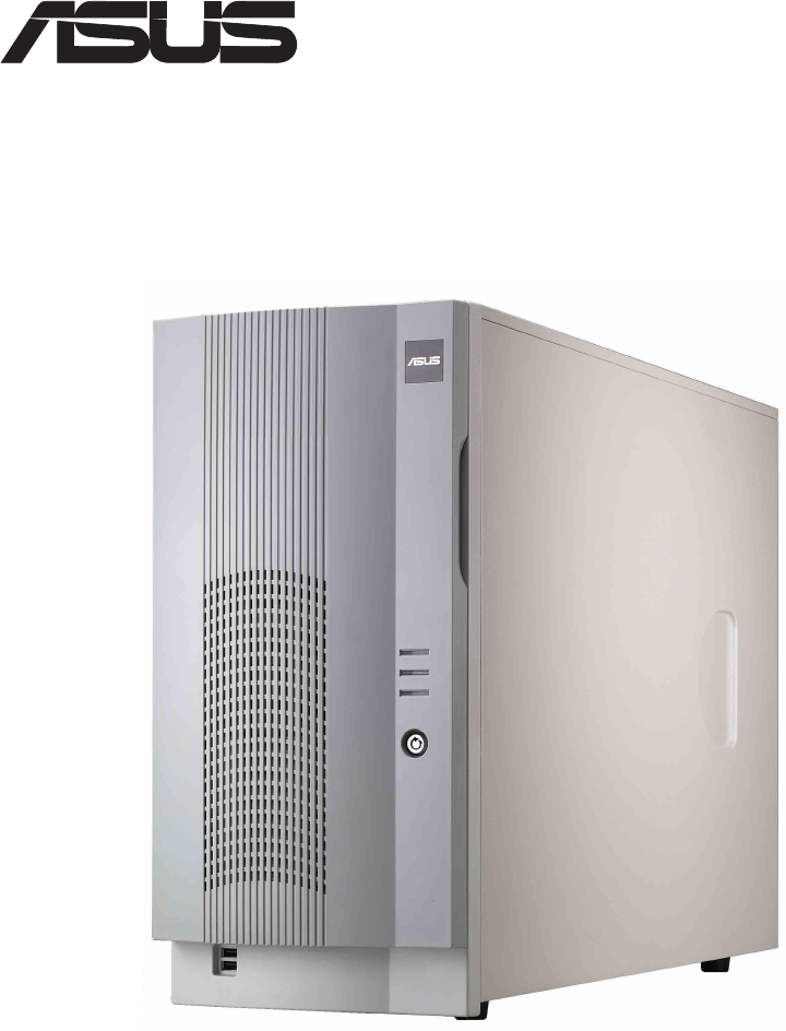
Intel® Xeon Tower/5U Rackmount Server®AP1700User’s Manualwith 533MHz FSB support
I-2 ASUS AP1700AudienceContentsThis guide contains the following parts:1. Introduction: About this guide This part introduces the contents of this
User’s Manual I-3ConventionsSymbolsTo make sure that you perform certain tasks properly, take note of thefollowing symbols used throughout this manual
I-4 ASUS AP1700System Package ContentsThe following checklist enumerates the components included in thestandard system package.1) ASUS AS-35 Tower/5U
User’s Manual 1-1Chapter 1System OverviewThis chapter describes the general features ofthe AP1700 system server. It includes sectionson front panel,
1-2 ASUS AP17001.1 System FeaturesThe ASUS AP1700 server is a stylish server system featuring theASUS PR-DLS533 motherboard. The server supports the I
User’s Manual 1-31.2 Front Panel FeaturesThe front panel allows easy access to the hard disk drives. The powerand reset buttons, LED indicators, optic
1-4 ASUS AP17001.3 Rear Panel FeaturesThe server rear panel includes the connectors, the system devices,a chassis lock and six full-length expansion c
User’s Manual 1-51.4 Internal FeaturesThe standard components inside the server include the motherboard,power supply, floppy and CD-ROM drives, and ca
1-6 ASUS AP17001.5 LED TableThe following table describes the LED display found on the front paneland rear panel of the AP1700 server system.
User’s Manual 2-1Chapter 2Hardware SetupThis chapter lists the hardware setupprocedures that you have to perform wheninstalling system components.
ii ASUS AP1700Disclaimer/CopyrightsNo part of this manual, including the products and software described in it, may bereproduced, transmitted, transcr
2-2 ASUS AP17002.1 Removing and installing chassis coverThe chassis is designed for easy assembly and disassembly, making theinstallation of internal
User’s Manual 2-32.1.2 Installing the cover1. Match and insert the hooks of the cover to the elongated holes on the side of the chassis. All the si
2-4 ASUS AP17002.2 Motherboard placementBefore you install the motherboard, study the configuration of your chassisto ensure that the motherboard fits
User’s Manual 2-52.3 Installing the Central Processing Unit (CPU)2.3.1 OverviewThe motherboard comes with dual surface mount 604-pin Zero InsertionFor
2-6 ASUS AP1700Follow these steps to install a CPU.1. Locate the 604-pin ZIF sockets onthe motherboard. Unlock thesocket by pressing the leversideways
User’s Manual 2-7The Intel® Xeon™ processors require especially designed heatsink andfan assembly to ensure optimum thermal condition and performance.
2-8 ASUS AP17004. Make sure that the heatsink andfan assembly is stable in placeand the fan power cable areconnected properly.5. If you wish to instal
User’s Manual 2-92.4 System memory2.4.1 OverviewThe motherboard comes with six Double Data Rate (DDR) Dual InlineMemory Module (DIMM) sockets. These s
2-10 ASUS AP17002.4.2 Memory ConfigurationsThe motherboard supports system memory of up to 12GB in a two-wayinterleaved configuration. As a rule, this
User’s Manual 2-112.4.3 Installing a DIMMMake sure to unplug the power supply before adding or removingDIMMs or other system components. Failure to do
User’s Manual iiiASUS Contact InformationASUSTeK COMPUTER INC. (Asia-Pacific)Address: 150 Li-Te Road, Peitou, Taipei, Taiwan 112General Tel: +886-2-28
2-12 ASUS AP17002.5 Fixed Device Bays2.5.1 OverviewThe fixed device bay are cinched by screwless locks for device placementconvenience. An IDE CD-ROM
User’s Manual 2-132.5.2 Installing a 5.25 deviceMake sure to unplug the AC power supply before adding or removingany 5.25 fixed device or other system
2-14 ASUS AP17002. Remove the appropriatemetallic bay panel cover ofthe bay slot you want toinstall your device.3. From the side of the drive bay,
User’s Manual 2-155. Carefully insert device (suchas CD/DVD-ROM drive) intothe selected bay.6. Secure the drive to the bay using the screwless dri
2-16 ASUS AP17002.5.3 Removing floppy disk drive tray2. Remove the two screws thatsecure the right side chassiscover.Follow the following procedures t
User’s Manual 2-174.a Carefully detach thefloppy disk drive cable.4.b Carefully detach thefloppy disk drive powercable.5. Pull out the floppy disk dri
2-18 ASUS AP17002.6 Installing a Hard Disk DriveThe server comes with six externally accessible drive bays. In each of thedrive bays is a removable tr
User’s Manual 2-191. Place an SCA SCSI hard drive into drive tray and secure the drive using the bundled four (4) screws.2. After the drive is secu
2-20 ASUS AP17002.7 Screwless Expansion Card SlotThe AP1700 chassis is designed with a screwless expansion card slot forPersonal Computer Interface (P
User’s Manual 2-212.8 Long Card Support GuideThe long card support guide secures that long expansion cards arepositioned firmly in place.Make sure to
iv ASUS AP1700FCC/CDC StatementsFederal Communications CommissionThis device complies with FCC Rules Part 15. Operation is subject to thefollowing two
2-22 ASUS AP17002.9 RAID Card (optional)The following picture shows the proper cabling of an installed RAID card. Itis recommended that the given RAID
User’s Manual 2-232.10 Hard Drive BlowerThe hard drive module is cooled by a blower mounted under the hot swapbays.The drive blower status can be moni
2-24 ASUS AP17002.11 Chassis FanThe chassis is cooled by a 12-cm chassis fan mounted at the rearpanel.The chassis fan status can be monitored remotely
User’s Manual 2-252.12 Connecting CablesMost of the cables in the server are already pre-connected to theirrespective connectors. The following illust
2-26 ASUS AP17002.13 SCSI Backplane2.13.1 OverviewThe SCSI backplane assembly defines the distribution of power and signalsto the system and its perip
User’s Manual 2-272.13.2 SCSI Backplane frontside and backsideThe SCSI backplane assembly of this server is comprised of one SCSIboard (BP6LS-AS35) w
2-28 ASUS AP1700
User’s Manual A-1Appendix AChassis Roller-wheelThis appendix contains the installationprocedure for the optional chassis roller-wheelunits for the AP1
A-2 ASUS AP1700Chassis Roller-wheel InstallationThe AP1700 comes with an optional roller-wheel for the chassis for servertransport convenience. Follow
User’s Manual A-3Appendix BPower ModulesThis appendix contains detailed hardwareoperation and specifications of the AP1700redundant power modules.
User’s Manual vContentsDisclaimer/Copyrights ... iiASUS Contact Information ...
A-4 ASUS AP1700Redundant Power ModulesThe redundant power model has two power supply modules. This hotswap power module can be removed or installed wh
User’s Manual A-5Redundant Power Module SpecificationsOutput Voltage RegulationOutput Current CapacityOver-Voltage Protection (OVP)Output Voltage Min
A-6 ASUS AP1700Removing Power Supply caseThe redundant power modules are secured in a power supply case thatconnects to various power supply connector
User’s Manual A-76. Remove the six (6)power case top screws.5. Remove the four (4) powercase side screws.Make sure the power case is well supported or
A-8 ASUS AP1700
User’s Manual A-9Appendix CTroubleshootingThis appendix lists the common problems thatyou may encounter while using the AP1700server system. It lists
A-10 ASUS AP1700TroubleshootingThe power LED on the serverand/or the monitor do not lightup1. Check the power cableconnection on the system rearpanel
User’s Manual A-11The system continuously beepsafter it was turned on1. Check the memory modulesand make sure you installedthe correct DIMMs the syste
A-12 ASUS AP1700
vi ASUS AP17002.7 Screwless Expansion Card Slot ... 2-202.8 Long Card Support Guide...
User’s Manual viiSafety PrecautionsElectrical SafetyOperation SafetyThis product is equipped with a three-wire power cable and plugfor the user’s safe
viii ASUS AP1700
User’s Manual I-1IntroductionAbout this guide“About This Guide” introduces the contentsof this document. This part includes thetarget audience, chapte
Produits connexes et manuels pour Serveurs Asus AP1700
 (206 pages)
 (94 pages)
(218 pages)
(188 pages)
(45 pages)
(193 pages)
(120 pages)
(32 pages)
(112 pages)
(94 pages)
(218 pages)
(188 pages)
(45 pages)
(193 pages)
(120 pages)
(32 pages)
(112 pages)
© 2020, manymanuals.fr. Tous droits réservés | 0.729 s |
 Manymanuals.com
 Manymanuals.de
 Manymanuals.fr
 Manymanuals.it
 Manymanuals.pl
 Manymanuals.cz
 Manymanuals.es
 Manymanuals-pt.com
Commentaires sur ces manuels