Asus V3-P5G31 Manuel d'utilisateur
Naviguer en ligne ou télécharger Manuel d'utilisateur pour Ordinateurs Asus V3-P5G31. Asus V3-P5G31 User Manual Manuel d'utilisatio
- Page / 99
- Table des matières
- MARQUE LIVRES
Noté. / 5. Basé sur avis des utilisateurs
- V-Series P5G31 1
- First Edition V1 2
- November 2007 2
- Table of contents 3
- Safety information 7
- About this guide 8
- Wheretondmoreinformation 9
- System package contents 10
- System introduction 11
- 1.1 Welcome! 12
- 1.2 Front panel 12
- 1-3ASUS V-Series P5G31 13
- 1.3 Rear panel 14
- Voltage selector 16
- 1.4 Internal components 17
- Basic installation 19
- 2.1 Preparation 20
- 2.2 Before you proceed 20
- panel assembly 21
- 2.4.1 Overview 22
- 2.4.2 Installing CPU 22
- 2-5ASUS V-Series P5G31 23
- CPU FAN PWR 25
- CPU FAN IN 25
- CPU FAN PWM 25
- 2.5 Installing a DIMM 26
- 2.5.1 Memorycongurations 27
- QualiedVendorsLists(QVL) 28
- DDR2 667 28
- DDR2 800 29
- 2.5.2 Installing a DDR2 DIMM 31
- 2.5.3 Removing a DDR2 DIMM 31
- 2.6 Expansion slots 32
- Standard interrupt assignment 33
- 2.6.3 PCI slots 34
- 2.6.4 PCI Express x1 slot 34
- 2.6.5 PCI Express x16 slot 34
- 2-17ASUS V-Series P5G31 35
- 2-19ASUS V-Series P5G31 37
- 2-21ASUS V-Series P5G31 39
- Floppy ribbon cable 40
- Power cable 40
- 2.11 Re-connecting cables 41
- 2.12 Reinstalling the cover 42
- Starting up 43
- 3.3 Support CD information 44
- 3.2 Powering up 44
- 3.3.1 Running the support CD 45
- 3.3.2 Utilities menu 46
- 3-5ASUS V-Series P5G31 47
- 3.4 Software information 48
- Preferences 49
- Hardware monitor panels 50
- WMI browser 51
- DMI browser 51
- PCI browser 52
- ConguringPCProbeII 53
- Motherboard introduction 54
- 4.1 Introduction 55
- 4.2 Motherboard layout 55
- Clear RTC 56
- (Default) 56
- 4.4 Connectors 58
- Orient the red markings 59
- (usually zigzag) on the ID 59
- Speaker Out Connector 60
- Fan Connectors 62
- Intrusion Connector 63
- System Panel Connector 65
- +HD LED RESET 65
- PLED PWRBTN 65
- BIOS setup 66
- DOS environment 67
- XP environment 67
- 2003 environment 67
- Vista environment 68
- 5.1.3 AFUDOS utility 69
- UpdatingtheBIOSle 70
- 5.1.5 ASUS Update utility 73
- ASUS V-Series P5G31 5-9 74
- 5.2 BIOS setup program 76
- 5.2.2 Menu bar 77
- 5.2.1 BIOS menu screen 77
- 5.2.3 Navigation keys 77
- ASUS V-Series P5G31 5-13 78
- 5.3 Main menu 79
- Type [Auto] 80
- LBA/Large Mode [Auto] 80
- 5.3.5 IDEConguration 81
- 5.3.6 System Information 82
- 5.4 Advanced menu 83
- Emulation Type [Auto] 84
- 5.4.3 CPUConguration 85
- PECI [Disabled] 86
- 5.4.4 Chipset 87
- VideoFunctionConguration 88
- SouthBridgeConguration 88
- HD Audio Controller [Azalia] 88
- Parallel Port IRQ [IRQ7] 89
- LAN Option ROM [Disabled] 89
- ECP Mode DMA Channel [DMA3] 89
- 5.4.6 PCI PnP 90
- 5.5 Power menu 91
- 5.5.4 APMConguration 92
- 5.5.5 Hardware Monitor 93
- 5.6 Boot menu 94
- 5-30 Chapter 5: BIOS setup 95
- 5.6.3 Security 96
- Change User Password 97
- Clear User Password 97
- Password Check [Setup] 97
- 5.7 Tools menu 98
- Exit Options 99
- Exit & Save Changes 99
- Exit & Discard Changes 99
- Discard Changes 99
- Load Setup Defaults 99
Résumé du contenu
Page 1 - V-Series P5G31
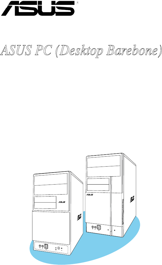
V-Series P5G31ASUS PC (Desktop Barebone)Installation ManualRR
Page 2 - November 2007
xSystem package contentsCheck your V-Series P5G31 system package for the following items.If any of the items is damaged or missing, contact your retai
Page 3 - Table of contents
RRSystem introductionThis chapter gives a general description of the ASUS V-Series P5G31. The chapter lists the system features including introduction
Page 4
1-2 Chapter 1: System introduction1.1 Welcome!Thank you for choosing the ASUS V-Series P5G31!The ASUS V-Series P5G31 is an all-in-one barebone system
Page 5
1-3ASUS V-Series P5G31This V-series provide V2/V3 two types of front panel for users to choose, please refer to your product package for the front pan
Page 6
1-4 Chapter 1: System introduction1.3 Rear panelThe system rear panel includes the power connector and several I/O ports that allow convenient connec
Page 7 - Safety information
1-5ASUS V-Series P5G318. USB 2.0 ports 1, 2, 3 and 4. These 4-pin Universal Serial Bus (USB) ports are available for connecting USB 2.0 devices.9. M
Page 8 - About this guide
1-6 Chapter 1: System introductionVoltage selectorThe PSU has a 115 V/230 V voltage selector switch located beside the power connector. Use this switc
Page 9 - Wheretondmoreinformation
1-7ASUS V-Series P5G3120.3cm (8in)24.5cm (9.6in)DDR2 DIMM_A1 (64 bit,240-pin module)DDR2 DIMM_B1 (64 bit,240-pin module)P5KPL-VMLAN_USB12AUDIOLGA775CP
Page 10 - System package contents
1-8 Chapter 1: System introduction
Page 11 - System introduction
Basic installationThis chapter provides step-by-step instructions on how to install components in the system.Chapter 2RR
Page 12 - 1.2 Front panel
iiCopyright © 2007 ASUSTeK COMPUTER INC. All Rights Reserved.No part of this manual, including the products and software described in it, may be repro
Page 13 - 1-3ASUS V-Series P5G31
2-2 Chapter 2: Basic installation 2.1 PreparationBefore you proceed, make sure that you have all the components you plan to install in the system.Bas
Page 14 - 1.3 Rear panel
2-3ASUS V-Series P5G312.3 Removing the side cover and front panel assembly1. Remove the cover screws on the rear panel.2. Pull the side cover
Page 15
2-4 Chapter 2: Basic installation 2.4 Central Processing Unit (CPU)2.4.1 Overview2.4.2 Installing CPUTo install a CPU:1. Locate the CPU socket on
Page 16 - Voltage selector
2-5ASUS V-Series P5G31To prevent damage to the socket pins, do not remove the PnP cap unless you are installing a CPU.2. Press the load lever with yo
Page 17 - 1.4 Internal components
2-6 Chapter 2: Basic installation 7. Close the load plate (A), then push the load lever (B) until it snaps into the retention tab.6. Apply Thermal I
Page 18
2-7ASUS V-Series P5G31If you purchased a separate CPU heatsink and fan assembly, make sure that the Thermal Interface Material is properly applied to
Page 19 - Basic installation
2-8 Chapter 2: Basic installation 2.5 Installing a DIMMThe motherboard comes with two Double Data Rate 2 (DDR2) Dual Inline Memory Modules (DIMM) soc
Page 20 - 2.2 Before you proceed
2-9ASUS V-Series P5G312.5.1 MemorycongurationsYou may install 256 MB, 512 MB, 1 GB and 2 GB unbuffered non-ECC DDR2 DIMMs into the DIMM sockets.•
Page 21 - panel assembly
2-10 Chapter 2: Basic installation QualiedVendorsLists(QVL) Size Vendor Model Brand Side(s) Part No. A B DIMM supportDDR2 667DIMM support
Page 22 - 2.4.2 Installing CPU
2-11ASUS V-Series P5G31DDR2 667 1G PSC AL7E8E63B-6E1K PSC DS A3R12E3GEF637BLC5N • • 256MB Nanya NT256T64UH4A1FY-3C Nanya SS NT5TU32M16AG-3
Page 23 - 2-5ASUS V-Series P5G31
iiiTable of contentsNotices ... viSafety informa
Page 24
2-12 Chapter 2: Basic installation Side(s): SS - Single-sided DS - Double-sided DIMM support:A - Supports one module inserted into any slot as S
Page 25 - CPU FAN PWM
2-13ASUS V-Series P5G312.5.2 Installing a DDR2 DIMMTo install a DIMM:1. Unlock a DIMM socket by pressing the retaining clips outward.2. Align a DIM
Page 26 - 2.5 Installing a DIMM
2-14 Chapter 2: Basic installation 2.6 Expansion slotsIn the future, you may need to install expansion cards. The following sub-sections describe the
Page 27 - 2.5.1 Memorycongurations
2-15ASUS V-Series P5G31* These IRQs are usually available for PCI devices.IRQ assignments for this motherboardA B C D E F G HPCI1 — — — shared — — —
Page 28 - DDR2 667
2-16 Chapter 2: Basic installation 2.6.3 PCI slotsThe PCI slots support cards such as a LAN card, SCSI card, USB card, and other cards that comply wi
Page 29 - DDR2 800
2-17ASUS V-Series P5G312.7 Installing an optical driveRefer to the instructions in this section if you wish to install a new optical drive.Follow the
Page 30
2-18 Chapter 2: Basic installation 7. Connect the other end of the IDE ribbon cable to the secondary IDE connector (labeled SEC_IDE) on the motherboa
Page 31 - 2.5.3 Removing a DDR2 DIMM
2-19ASUS V-Series P5G314. Connect a 15-pin Serial ATA power plug from the power supply unit to the 15-pin power connector at the back of the drive.-
Page 32 - 2.6 Expansion slots
2-20 Chapter 2: Basic installation 3. Connect the gray interface of the IDE ribbon cable to the IDE connector on the drive. 4. If you install two ID
Page 33 - Standard interrupt assignment
2-21ASUS V-Series P5G31To install the card reader module:1. Remove the drive slot metal plate cover.2. Carefully insert the card reader module into
Page 34 - 2.6.5 PCI Express x16 slot
ivTable of contentsChapter 3: Starting up3.1 Installing an operating system ... 3-23.2 Powering up
Page 35 - 2-17ASUS V-Series P5G31
2-22 Chapter 2: Basic installation 2. Carefully insert the oppy disk drive into the oppy drive bay until the screw holes align with the holes on th
Page 36
2-23ASUS V-Series P5G312.11 Re-connecting cablesYou may have disconnected some cables when you were installing components. You must re-connect these
Page 37 - 2-19ASUS V-Series P5G31
2-24 Chapter 2: Basic installation 2.12 Reinstalling the coverIf you installed an optical and/or oppy disk drive, remove the bay cover(s) on the fro
Page 38
Starting upThis chapter helps you power up the system and install drivers and utilities from the support CD.Chapter 3RR
Page 39 - 2-21ASUS V-Series P5G31
3-2 Chapter 3: Starting up3.1 Installing an operating systemThe barebone system supports Windows® 2000/XP operating systems (OS). Always install the
Page 40 - Power cable
3-3ASUS V-Series P5G313.3.1 Running the support CDTo begin using the support CD, place the CD in your optical drive. The CD automatically displays th
Page 41 - 2.11 Re-connecting cables
3-4 Chapter 3: Starting up3.3.2 Utilities menuThe Utilities menu shows the applications and other software that the motherboard supports. ASUS InstAl
Page 42 - 2.12 Reinstalling the cover
3-5ASUS V-Series P5G313.3.3 ASUS Contact informationClick the Contact tab to display the ASUS contact information. You can also nd this information
Page 43 - Starting up
3-6 Chapter 3: Starting up3.4 Software informationMost of the applications in the support CD have wizards that will conveniently guide you through th
Page 44 - 3.2 Powering up
3-7ASUS V-Series P5G31Button Function Opens the Conguration window Opens the Report window Opens the Desktop Management Interface window Opens t
Page 45 - 3.3.1 Running the support CD
vTable of contents5.3 Main menu ... 5-145.3.1 System Time ...
Page 46 - 3.3.2 Utilities menu
3-8 Chapter 3: Starting upHardware monitor panelsThe hardware monitor panels display the current value of a system sensor such as fan rotation, CPU te
Page 47 - 3-5ASUS V-Series P5G31
3-9ASUS V-Series P5G31Monitoring sensor alertThe monitor panel turns red when a component value exceeds or is lower than the threshold value. Refer to
Page 48 - 3.4 Software information
3-10 Chapter 3: Starting upPCI browserClick to display the PCI (Peripheral Component Interconnect) browser. This browser provides information on the
Page 49 - Preferences
3-11ASUS V-Series P5G31Memory usageThe Memory tab shows both used and available physical memory. The pie chart at the bottom of the window represents
Page 50 - Hardware monitor panels
Motherboard introductionThis chapter gives information about the motherboard that comes with the system. This chapter includes the motherboard layout,
Page 51 - DMI browser
4-2 Chapter 4: Motherboard info4.1 IntroductionThe Vintage V-Series P5G31 barebone system comes with an ASUS motherboard. This chapter provides techn
Page 52 - PCI browser
4-3ASUS V-Series P5G314.3 Jumpers1. Clear RTC RAM (CLRTC)This jumper allows you to clear the Real Time Clock (RTC) RAM in CMOS. You can clear the CM
Page 53 - ConguringPCProbeII
4-4 Chapter 4: Motherboard info2. USB device wake-up (3-pin PS2_USBPW)Set these jumpers to +5V to wake up the computer from S1 sleep mode (CPU stoppe
Page 54 - Motherboard introduction
4-5ASUS V-Series P5G314.4 Connectors1. Floppy disk drive connector (34-1 pin FLOPPY)This connector is for the provided oppy disk drive (FDD) signal
Page 55 - 4.2 Motherboard layout
4-6 Chapter 4: Motherboard info3. IDE connector (40-1 pin PRI_IDE)The onboard IDE connector is for the Ultra DMA 100/66/33 signal cable. There are th
Page 56 - (Default)
viNoticesFederal Communications Commission StatementThis device complies with Part 15 of the FCC Rules. Operation is subject to the following two cond
Page 57
4-7ASUS V-Series P5G314. Serial ATA connectors (7-pin SATA1, SATA2, SATA3, SATA4)These connectors are for the Serial ATA signal cables for Serial ATA
Page 58 - 4.4 Connectors
4-8 Chapter 4: Motherboard info6. USB connectors (10-1 pin USB56, USB78)These connectors are for USB 2.0 ports. Connect the USB module cable to any o
Page 59 - (usually zigzag) on the ID
4-9ASUS V-Series P5G318. CPU, chassis and power fan connectors (4-pin CPU_FAN, 3-pin CHA_FAN, 3-pin PWR_FAN)The fan connectors support cooling fans o
Page 60 - Speaker Out Connector
4-10 Chapter 4: Motherboard info10. Front panel audio connector (10-1 pin AAFP)This connector is for a chassis-mounted front panel audio I/O module t
Page 61
4-11ASUS V-Series P5G31• For a fully congured system, we recommend that you use a power supply unit (PSU) that complies with ATX 12 V Specication 2
Page 62 - Fan Connectors
4-12 Chapter 4: Motherboard info12. System panel connector (10-1 pin F_PANEL) This connector supports several chassis-mounted functions.• System po
Page 63 - Intrusion Connector
BIOS setupThis chapter tells how to change system settings through the BIOS Setup menus and describes the BIOS parameters.Chapter 5RR
Page 64
5-2 Chapter 5: BIOS setup5.1 Managing and updating your BIOSThe following utilities allow you to manage and update the motherboard Basic Input/Output
Page 65 - PLED PWRBTN
ASUS V-Series P5G31 5-3Windows® Vista environmenta. Insert a formatted, high density 1.44 MB oppy disk to the oppy disk drive. b. Click from th
Page 66 - BIOS setup
5-4 Chapter 5: BIOS setup5.1.3 AFUDOS utilityThe AFUDOS utility allows you to update the BIOS le in DOS environment using a bootable oppy disk with
Page 67 - 2003 environment
viiSafety informationElectrical safety• To prevent electrical shock hazard, disconnect the power cable from the electrical outlet before relocating th
Page 68 - Vista environment
ASUS V-Series P5G31 5-5UpdatingtheBIOSleTo update the BIOS le using the AFUDOS utility:1. Visit the ASUS website (www.asus.com) and download th
Page 69 - 5.1.3 AFUDOS utility
5-6 Chapter 5: BIOS setup5.1.4 ASUS CrashFree BIOS 3 utilityThe ASUS CrashFree BIOS 3 is an auto recovery tool that allows you to restore the BIOS l
Page 70 - UpdatingtheBIOSle
ASUS V-Series P5G31 5-7Recovering the BIOS from the support CDTo recover the BIOS from the support CD:1. Remove any oppy disk from the oppy disk d
Page 71
5-8 Chapter 5: BIOS setupInstalling ASUS UpdateTo install ASUS Update:1. Place the support CD in the optical drive. The Drivers menu appears. 2. Cli
Page 72
ASUS V-Series P5G31 5-93. Select the ASUS FTP site nearest you to avoid network trafc, or click Auto Select. Click Next.Updating the BIOS through t
Page 73 - 5.1.5 ASUS Update utility
5-10 Chapter 5: BIOS setupUpdatingtheBIOSthroughaBIOSleTo update the BIOS through a BIOS le:1. Launch the ASUS Update utility from the Window
Page 74 - ASUS V-Series P5G31 5-9
ASUS V-Series P5G31 5-11• The default BIOS settings for this motherboard apply for most conditions to ensure optimum performance. If the system beco
Page 75
5-12 Chapter 5: BIOS setup5.2.2 Menu barThe menu bar on top of the screen has the following main items:Main For changing the basic system congur
Page 76 - 5.2 BIOS setup program
ASUS V-Series P5G31 5-135.2.4 Menu itemsThe highlighted item on the menu bar displays the specic items for that menu. For example, selecting Main
Page 77 - 5.2.3 Navigation keys
5-14 Chapter 5: BIOS setup5.3 Main menuWhen you enter the BIOS Setup program, the Main menu screen appears, giving you an overview of the basic syste
Page 78 - ASUS V-Series P5G31 5-13
viiiAbout this guideAudienceThis guide provides general information and installation instructions about the ASUS Vintage V-Series P5G31 barebone syste
Page 79 - 5.3 Main menu
ASUS V-Series P5G31 5-155.3.4 Primary, Third and Fourth IDE Master/SlaveWhile entering Setup, the BIOS automatically detects the presence of IDE dev
Page 80 - LBA/Large Mode [Auto]
5-16 Chapter 5: BIOS setupPIO Mode [Auto]Selects the PIO mode. Conguration options: [Auto] [0] [1] [2] [3] [4]DMA Mode [Auto]Selects the DMA mode. C
Page 81 - 5.3.5 IDEConguration
ASUS V-Series P5G31 5-175.3.6 System InformationThis menu gives you an overview of the general system specications. The BIOS automatically detects
Page 82 - 5.3.6 System Information
5-18 Chapter 5: BIOS setup Select Screen Select ItemEnter Go to Sub-screenF1 General HelpF10 Save and ExitESC Exit5.4 Advanced menu
Page 83 - 5.4 Advanced menu
ASUS V-Series P5G31 5-19The Module Version and USB Devices Enabled items show the auto-detected values. If no USB device is detected, the item shows
Page 84 - Emulation Type [Auto]
5-20 Chapter 5: BIOS setup5.4.3 CPUCongurationThe items in this menu show the CPU-related information that the BIOS automatically detects. Op
Page 85 - 5.4.3 CPUConguration
ASUS V-Series P5G31 5-21Vanderpool Technology [Enabled]Enables or disables Intel Virtualization Technology. Virtualization enhanced by Intel® Virtual
Page 86 - PECI [Disabled]
5-22 Chapter 5: BIOS setup5.4.4 ChipsetThe Chipset menu allows you to change the advanced chipset settings. Select an item then press <Enter> t
Page 87 - 5.4.4 Chipset
ASUS V-Series P5G31 5-23VideoFunctionCongurationVideo Function Conguration DVMT Mode Select [DVMT Mode] DVMT/FIXED Memory [256MB]DVMT Mode Se
Page 88 - HD Audio Controller [Azalia]
5-24 Chapter 5: BIOS setup5.4.5 OnboardDevicesCongurationCongure Win627DHG-A Super IO ChipsetOnboard PCIE GbE LAN [Enabled] LAN Option ROM [D
Page 89 - ECP Mode DMA Channel [DMA3]
ixConventions used in this guideWARNING: Information to prevent injury to yourself when trying to complete a task. CAUTION: Information to prevent dam
Page 90 - 5.4.6 PCI PnP
ASUS V-Series P5G31 5-255.4.6 PCI PnPThe PCI PnP menu items allow you to change the advanced settings for PCI/PnP devices. The menu includes setting
Page 91 - 5.5 Power menu
5-26 Chapter 5: BIOS setup Select Screen Select Item+- Change OptionF1 General HelpF10 Save and ExitESC Exit5.5 Power menuThe Pow
Page 92 - 5.5.4 APMConguration
ASUS V-Series P5G31 5-275.5.4 APMCongurationAPM CongurationPower Button Mode [On/Off] Restore on AC Power Loss [Power Off]Power
Page 93 - 5.5.5 Hardware Monitor
5-28 Chapter 5: BIOS setupPower On By PS/2 Keyboard [Disabled]Allows you to use specic keys on the keyboard to turn on the system. This feature requi
Page 94 - 5.6 Boot menu
ASUS V-Series P5G31 5-29 Select Screen Select ItemEnter Go to Sub-screenF1 General HelpF10 Save and ExitESC ExitChassis Fan Speed [x
Page 95 - 5-30 Chapter 5: BIOS setup
5-30 Chapter 5: BIOS setup5.6.2 BootSettingsConguration Select Screen Select Item+- Change OptionF1 General HelpF10 Save and ExitESC
Page 96 - 5.6.3 Security
ASUS V-Series P5G31 5-31If you forget your BIOS password, you can clear it by erasing the CMOS Real Time Clock (RTC) RAM. See section “1.9 Jumpers” f
Page 97 - Password Check [Setup]
5-32 Chapter 5: BIOS setupAfter you have set a supervisor password, the other items appear to allow you to change other security settings. User Access
Page 98 - 5.7 Tools menu
ASUS V-Series P5G31 5-335.7 Tools menuThe Tools menu items allow you to launch special functions. Select an item then press <Enter> to display
Page 99 - Load Setup Defaults
5-34 Chapter 5: BIOS setupExit system setupafter saving thechanges.F10 key can be usedfor this operation. Select Screen Select ItemEnter Go
Plus de documents pour Ordinateurs Asus V3-P5G31

Asus V3-P5G31 Manuel d'utilisateur
(2 pages)
Produits connexes et manuels pour Ordinateurs Asus V3-P5G31
Ordinateurs Asus BT6130 Manuel d'utilisateur
 (54 pages)
(54 pages)
Ordinateurs Asus CM6650 Manuel d'utilisateur
(84 pages)
(84 pages)
Ordinateurs Asus V3-M3N8200 Manuel d'utilisateur
 (108 pages)
(108 pages)
Ordinateurs Asus BP1AD Manuel d'utilisateur
 (86 pages)
(86 pages)


Ordinateurs Asus BM6620 Manuel d'utilisateur
(70 pages)
(70 pages)
Ordinateurs Asus BM5368 Manuel d'utilisateur
(26 pages)
(26 pages)
 (2 pages)
Ordinateurs Asus P1801 Manuel d'utilisateur
 (62 pages)
(62 pages)
Ordinateurs Asus CM1730 Manuel d'utilisateur
(200 pages)
(200 pages)

Ordinateurs Asus P30AD Manuel d'utilisateur
(64 pages)
(64 pages)
© 2020, manymanuals.fr. Tous droits réservés | 1.852 s |
 Manymanuals.com
 Manymanuals.de
 Manymanuals.fr
 Manymanuals.it
 Manymanuals.pl
 Manymanuals.cz
 Manymanuals.es
 Manymanuals-pt.com
Commentaires sur ces manuels